
Trang chủ
/
Thiết Bị Tổng Hợp
/
Thiết Bị Tự Động Hóa
/
HMI, Thiết Đị Điều Khiển
/
Mô Đun Điều Khiển CEV.47
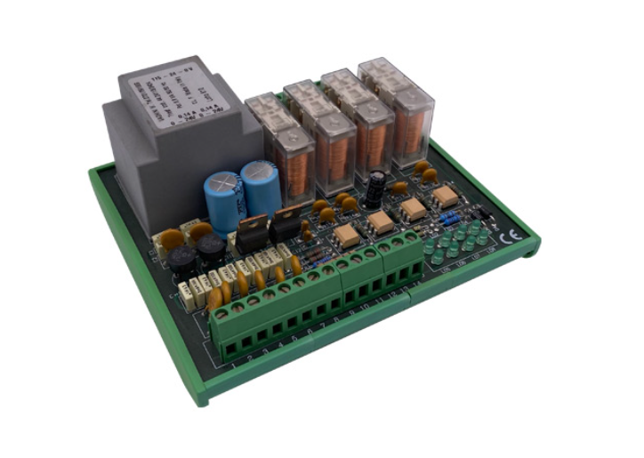
- Mô Đun Điều Khiển CEV.47
- Model: CEV.47
- Hãng: PAOLO COLOMBO
Nguồn: 24 – 110V. 50 HZ +/- 10%.
Công suất nạp: xấp xỉ 15VA.
Cụm ray: DIN 35 mm.
Cấp độ bảo vệ: IP 20.
Hạng mục an toàn: EN 954.
Thời gian đồng bộ: xấp xỉ 100 ms.
Nhiệt độ: -10° +55°C.-
Bảng giá sản phẩm
Số lượng Giá bán (VNĐ) 1+ Liên hệ 5+ Liên hệ 10+ Liên hệ 15+ Liên hệ Chưa bao gồm VAT
Thông tin đặt hàngLiên hệ
Tối thiểu: 1Đặt hàng
- Mô tả chi tiết
- Thông số kỹ thuật
- Bình luận
CEV.47 VALVE CONTROL MODULE
Compliant with current regulations
The CEV.47 valve control module is used to increase press safety according to European Standard EN 692 specifications, namely:

Technical specifications
√ Power: 24 – 110V. 50 HZ +/- 10%.
√ Intake power: approximately 15VA.
√ Rail assembly: DIN 35 mm.
√ Degree of protection: IP 20.
√ Safety category: EN 954.
√ Synchronisation time: approximately 100 ms.
√ Safety outputs: two override contacts 1 NC + 1 NO 6A.
√ Working temperature range: -10° +55°C.
Operathing conditions
The CEV.47 module continuously checks valve symmetry, i.e.:
A) Power voltage symmetry of the two windings.
B) Response time symmetry of the two solenoid valves with lock option in the event of excessive difference between valve energising times.
C) Exact correlation between wiring voltage and position of the cylinders.
The machine is stopped if one of these situations is irregular and/or if any other asymmetric condition occurs. Furthermore, the machine is stopped in the event of a blackout or missed continued in wiring between proximity switches and/or mechanical limit switches and control unit. The machine can be started after repairing the failure and resetting the fault by means of a reset key button.
LEDs indicating the following are found on the front of the CEV.47 control valve control module:
Valve 1 power
Valve 2 power
SV1 cylinder failure
SV2 cylinder failure
Synchronism control down
Valve control OK
Reset key button control
Valves working.
Asymmetric conditions may occur at any time, not only when the machine is running or is stopped, e.g. also in the case of broken wiring to the solenoid valve and/or burnt relay contact.
Description
Use of the CEV.47 module requires a machine control (CEV.4) with safe stop at top dead centre and automatic control of brake stroke at each cycle. The position of the valve cylinders is controlled by mechanical contracts or proximity switches. For this operation, the CEV.47 can be connected to PNP switches (two or three wires) or mechanical contracts with the possibility of the activating the module related at a winding power of approximately 0.5 W each. The wiring diagram shown below shows that when the valve windings are at rest, the switches are on. In this way, it is possible to check whether the valve has been powered in locked position at the beginning of each cycle.
Operation
Thanks to CEV.47 redundant system valve implementation, it is unlikely for the two valves to be effected at the same time. Since it is impossible to foresee which of the two valves will breakdown, simultaneous disconnection is controlled by proximity switches and/or mechanical limit switches in a time equal to approximately 100 milliseconds, to prevent powering up if this value is exceeded. If clutch and brake are assembled separately, each device will need its own valve which will need to be controlled separately. In this condition, the CEV.47 outputs will be fitted in series. The reset key button will be wired to terminals 9-10, allowing to solve a failure and restore original conditions without fully cutting off the controller circuit. Connecting a normally closed power contact controlling the machine motor in parallel to the reset key button the reset function can be made automatic at the first machine cycle after power up. The CEV.47 module is equipped with four semiconductor outputs, which are used to signal operation status to a PLC:
√ 13 (control power voltage)
√12 (valve 1 jammed)
√11 (valve 2 jammed)
√10 (synchronism control down)
Surveillance must be dynamic, with a frequency of at least one check per cycle, and must ensure that in the event of a failure concerning one or more solenoid valves the system engages the clutch and applies the brake.
The solenoid valves must be connected to the control circuit by means of separate wiring harnesses so that a single failure in the wiring cannot operate the solenoid valves.
A short-circuit occurring between safety valve connections (e.g. between solenoid valves or between solenoid valve and surveillance system) must be identified automatically without causing additional or unexpected movement of the machine.
Where sensors are used for surveillance to detect valve status, these sensors must be an integral part of the valve. The valve can have an intrinsic surveillance system to automatically detect valve failures.
The press must be equipped with at least two single solenoid valves or one double solenoid valve to directly control fluid flow to the controlled brake/clutch unit.
Sản phẩm cùng loại

EATON 046938 Motorschutzschalter, 3-polig, Ir = 10 - 16 A, Schraubanschluss
50.000 VNĐ 60.000 VNĐ
Xem chi tiết