
- Van Điều Khiển Áp Suất UV 8.2
- Model: UV 8.2
- Hãng: MANKENBERG
Kết nối DN: 15-50
Kết nối G: 3/8 - 2
Áp suất danh nghĩa PN: 100
Áp suất đầu vào: 2 - 100 bar
Kvs-value: 0,2 - 5,5 m³ / h
Nhiệt độ: 400 ° C-
Bảng giá sản phẩm
Số lượng Giá bán (VNĐ) 1+ Liên hệ 5+ Liên hệ 10+ Liên hệ 15+ Liên hệ Liên hệ
Thông tin đặt hàngLiên hệ
Tối thiểu: 1Đặt hàng
- Mô tả chi tiết
- Thông số kỹ thuật
- Bình luận
PRESSURE CONTROL
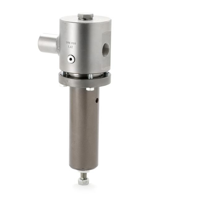
Back pressure regulators UV 8.2
High pressure valve for small and medium flow rates

Technical data
Connection DN 15 - 50
Connection G 3/8 - 2
Nominal pressure PN 100
Inlet pressure 2 - 100 bar
Kvs-value 0.2 - 5.5 m³/h
Temperature 400 °C
Medium liquid, gases and steam
*RT = -10 °C up to + 50 °C
Description
Self-acting back pressure regulators are simple control valves offering accurate control while being easy to install and maintain. They control the pressure upstream of the valve without requiring pneumatic or electrical control
elements.
The UV 8.2 backpressure regulator is a diaphragm, piston or bellows-controlled spring-loaded proportional control valve for high pressures and small
volumes. It can be supplied with three types of connections: sockets, flanges
and welding spigots. Each size of valve may be fitted with three different
seats. The valve cone may be fitted with a soft or metallic seal.
The inlet pressure to be controlled is balanced across the valve seat by the
force of the valve spring (set pressure). If the inlet pressure rises above the
set pressure, the valve opens. With decreasing inlet pressure the valve control orifice reduces. When the pipeline is depressurised, the valve is closed.
Rotating the adjusting screw clockwise increases the inlet pressure.
These valves are no shut-off elements ensuring a tight closing of the valve.
In accordance with DIN EN 60534-4 and/or ANSI FCI 70-2 they may feature
a leakage rate in closed position in compliance with the leakage classes III
or V, optional IV.
Standard
» Metallic valve seal
Options
» Pressure gauge connection
» Soft seal
» Hard-faced valve cone and seat
» For toxic or hazardous media: sealed bonnet complete with leakage line
connection (incl. sealed adjusting screw). Must be installed with a leakage line capable of draining leaking medium safely and without pressure
» Various diaphragm and seal materials suitable for your medium
» Special materials such as Duplex, Superduplex, Hastelloy® or titanium,
others on request
» Special connections: ANSI or JIS flanges, NPT, welding spigots; other
connections on request
» Special versions on request
Technical specification
| Kvs values [m3/h] | ||||||||
| nominal diameter | G | 3/8 | 1/2 | 3/4 | 1 | 1 1/4 | 1 1/2 | 2 |
| DN | 15 | 20 | 25 | 32 | 40 | 50 | ||
| seat | I | 0.2 | 0.2 | 0.25 | 0.25 | 0.4 | 0.4 | 1 |
| II | 0.9 | 0.9 | 0.9 | 0.9 | 2.5 | 2.5 | 3.5 | |
| III | 1.7 | 1.8 | 2 | 2.2 | 3.9 | 3.9 | 5.5 |
| Setting ranges [bar], nominal pressure* | ||||||
| setting range | bar | 2 - 4 | 4 - 7 | 7 - 10 | 5 - 16 | 10 - 20 |
| nominal pressure | PN | 6 | 16 | 16 | 25 | 25 |
| Setting ranges [bar], nominal pressure* | ||||||
| setting range | bar | 10 - 25 | 20 - 35 | 35 - 50 | 45 - 63 | 60 - 100 |
| nominal pressure | PN | 40 | 63 | 100 | 100 | 100 |
* inlet and outlet pressure
| Materials | ||
| Temperature | 130 °C | 400 °C |
| Body | G 3/8 - 1, DN 15 - 25 = C steel G 1 1/4 - 2, DN 32 - 50 = Steel welded Optional CrNiMo-steel for all diameters |
|
| Bonnet | Steel welded optional stainless steel | |
| Internals | Stainless steel | Stainless steel |
| Spring | Stainless steel | Stainless steel |
| Soft seal | EPDM optional FKM or PTFE |
- |
| Diaphragm | EPDM optional FKM | - |
| Protection foil | PTFE (option) | - |
| O-ring for piston | EPDM optional FKM | - |
| Bellow | - | Stainless steel |
| Dimensions [mm] globe design | ||||
| size | nominal diameter | |||
| G 3/8 | G 1/2 | G 3/4 | G 1 | |
| - | DN 15 | DN 20 | DN 25 | |
| A* | 110 | 110 | 110 | 110 |
| A1* | 220 | 220 | 220 | 220 |
| B | 30 | 30 | 30 | 30 |
| C | 420 | 420 | 420 | 420 |
| Dimensions [mm] elbow design | ||||
| size | nominal diameter | |||
| G 3/8 - 1 | G 1 1/4 | G 1 1/2 | G 2 | |
| DN 15 - 25 | DN 32 | DN 40 | DN 50 | |
| A* | 55 | 100 | 100 | 100 |
| A1* | 110 | ** | ** | ** |
| B* | 65 | 108 | 108 | 108 |
| B1* | 120 | ** | ** | ** |
| C | 420 | 650 | 650 | 650 |

