

- Van Điều Khiển Áp Suất UV 5.1
- Model: UV 5.1
- Hãng: MANKENBERG
Kết nối DN: 15-50
Kết nối G: 1/2 - 2
Áp suất danh nghĩa PN: 16
Áp suất đầu vào: 0,02 - 12 bar
Kvs-value: 3,5 - 22 m³ / h
Nhiệt độ: 130 ° C-
Bảng giá sản phẩm
Số lượng Giá bán (VNĐ) 1+ Liên hệ 5+ Liên hệ 10+ Liên hệ 15+ Liên hệ Chưa bao gồm VAT
Thông tin đặt hàngLiên hệ
Tối thiểu: 1Đặt hàng
- Mô tả chi tiết
- Thông số kỹ thuật
- Bình luận
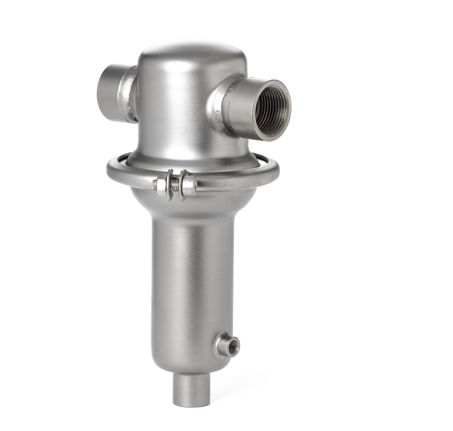
PRESSURE CONTROL
Back pressure regulators UV 5.1
Universal valve
Technical data
Connection DN 15 - 50
Connection G 1/2 - 2
Nominal pressure PN 16
Inlet pressure 0.02 - 12 bar
Kvs-value 3.5 - 22 m³/h
Temperature 130 °C
Medium liquids and gases
*RT = -10 °C up to + 50 °C
Description
Self-acting back pressure regulators are simple control valves offering accurate control while being easy to install and maintain. They control the pressure upstream of the valve without requiring pneumatic or electrical control
elements.
The UV 5.1 backpressure regulator is a spring-loaded diaphragm-controlled
and balanced proportional control valve for universal application. This bypass valve is manufactured from deep-drawn stainless steel featuring excellent corrosion resistance. The valve cone is fitted with a soft seal.
The spring module comprising bonnet, spring, adjusting screw, diaphragm
and internal components, is connected to the valve body only by means of a
clamp ring and two bolts. Changing the diaphragm or the complete spring
assembly for a different control pressure range is extremely simple and does
not call for special tools. The same applies to servicing and maintenance.
The inlet pressure to be controlled is balanced across the valve seat by the
force of the valve spring (set pressure). If the inlet pressure rises above the
set pressure, the valve opens. With decreasing inlet pressure the valve control orifice reduces. When the pipeline is depressurised, the valve is closed.
Rotating the adjusting screw clockwise increases the inlet pressure.
The valve requires a sense line (to be installed on-site).
These valves are no shut-off elements ensuring a tight closing of the valve.
In accordance with DIN EN 60534-4 and/or ANSI FCI 70-2 they may feature
a leakage rate in closed position in compliance with the leakage classes V.
Standard
» All stainless steel construction
» Quick-release body clamp ring
Options
» Pressure gauge connection
» Electro-pneumatic actuation
» For toxic or hazardous media: sealed bonnet complete with leakage line
connection (incl. sealed adjusting screw). Must be installed with a leakage line capable of draining leaking medium safely and without pressure
» Various diaphragm and seal materials suitable for your medium
» Special connections: Aseptic, ANSI or JIS flanges, NPT, welding spigots;
other connections on request
» Special versions on request
Technical specification
| Kvs values [m3/h] | |||||||
| nominal diameter | DN | 15 | 20 | 25 | 32 | 40 | 50 |
| G | 1/2 | 3/4 | 1 | 1 1/4 | 1 1/2 | 2 | |
| Kvs value | [m3/h] | 3.5 | 3.5 | 4 | 22 | 22 | 22 |
| Setting ranges [bar], nominal pressure | ||||||||
| setting range | bar | 6 - 12 | 4 - 8 | 2 - 5 | 0.8 - 2.5 |
0.3 - 1.1 |
0.1 - 0.5 |
0.02 - 0.12 |
| nominal pressure | PN | 16 | 16 | 10 | 6 | 2.5 | 1 | 1 |
| Materials | |
| Temperature | 130 °C |
| Body, Internals , Bonnet, Screws, Adjusting screw |
Stainless steel |
| Spring | Stainless steel |
| Valve seal | EPDM optional FKM or PTFE |
| Diaphragm | EPDM optional FKM |
| O-ring | EPDM optional FKM |
| Dimensions sleeve connection | |||||||
| setting range bar |
size | nominal diameter | |||||
| G 1/2 | G 3/4 | G 1 | G 1 1/4 | G 1 1/2 | G 2 | ||
| DN 15 | DN 20 | DN 25 | DN 32 | DN 40 | DN 50 | ||
| all ranges | A* | 90 | 90 | 136 | 130 | 145 | 185 |
| A1* | 200 | 200 | 200 | 180 | 200 | 230 | |
| B | 40 | 40 | 40 | 110 | 110 | 110 | |
| 0.02 - 0.12 | C | 270 | 270 | 270 | 285 | 285 | 285 |
| D | 360 | 360 | 360 | 360 | 360 | 360 | |
| 0.1 - 0.5 | C | 270 | 270 | 270 | 285 | 285 | 285 |
| D | 264 | 264 | 264 | 264 | 264 | 264 | |
| 0.3 - 1.1 | C | 270 | 270 | 270 | 285 | 285 | 285 |
| D | 200 | 200 | 200 | 200 | 200 | 200 | |
| 0.8 - 12 | C | 205 | 205 | 205 | 218 | 218 | 218 |
| D | 138 | 138 | 138 | 138 | 138 | 138 |
*overall length tolerances in acc. with DIN EN 558
| Weights [kg] | ||||
| setting range bar |
nominal diameter | |||
| G 1/2 - 1 | G 1 1/4 - 2 | DN 15 - 25 | DN 32 - 50 | |
| 0.02-0.12 | 13 | 14.4 | 14 | 16.4 |
| 0.1 - 0.5 | 6.5 | 8 | 7.5 | 10 |
| 0.3 - 1.1 | 5.5 | 7 | 6.5 | 9 |
| 0.8 - 12 | 2.5 | 4 | 3.5 | 6 |
| Customs tariff number |
| 84814010 |

